Router on a stick is a network configuration used to allow the routing of traffic between different VLANs.
Almost all enterprise networks use VLANs which stands for Virtual Local Area Network. Each VLAN is a separate subnet and in order to route IP packets in and out of those VLANs – or more accurately, the subnets that sit on each of those VLANs – some router needs to have an IP address in each subnet and have a connected route for each of those subnets. The hosts inside each subnet can then use the router IP addresses as their default gateways, respectively.
There are three options available for connecting a router to each subnet on a VLAN:
- Use a router, with one router LAN interface and cable connected to the switch for each and every VLAN (typically not used).
- Use a router with a VLAN trunk connected to a LAN switch
- Use a Layer 3 switch
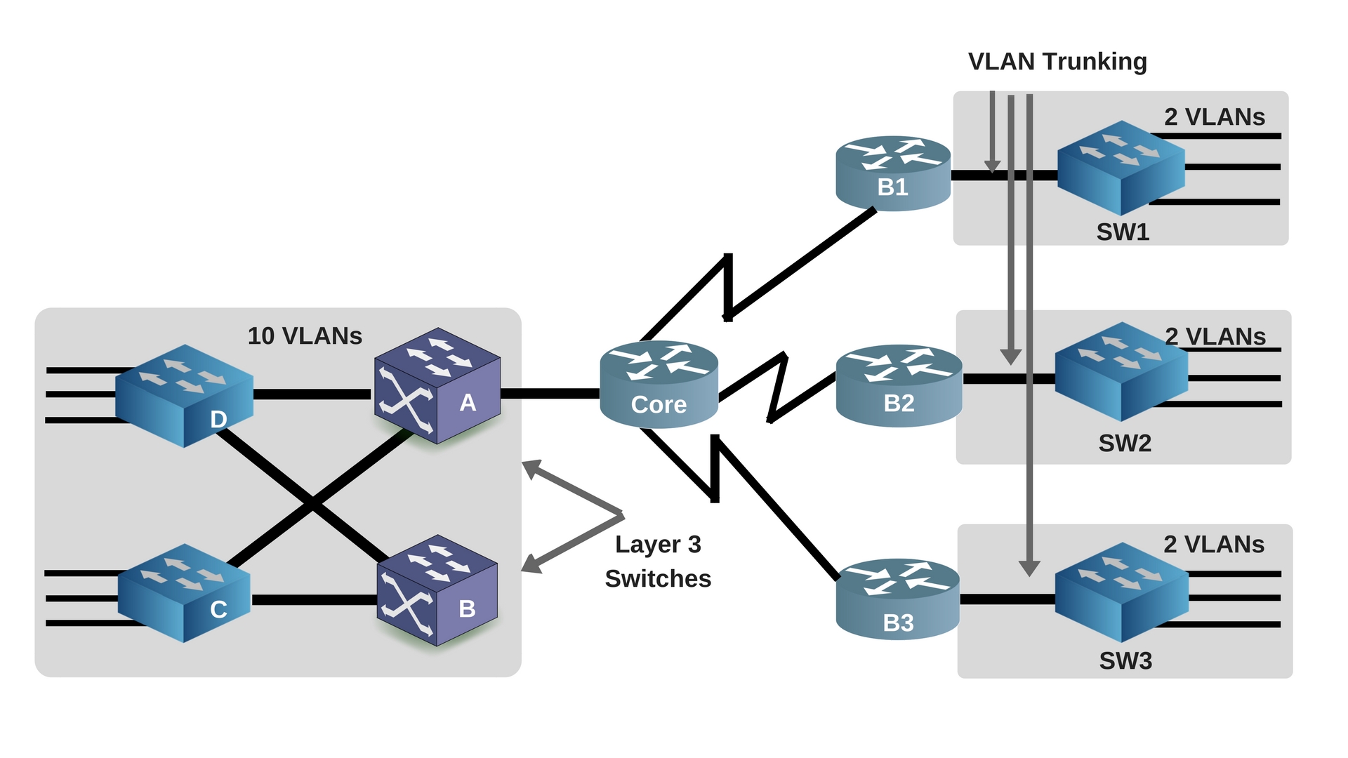
The example network below shows what the second and third option looks like. The figure shows a central site campus LAN on the left with 10 VLANs. Two of the switches act as Layer 3 switches, combining the functions of a router and a switch, routing between all 12 subnets/VLANs. And on the right side of the figure, each router has a VLAN trunk to connect and route for both VLANs.

Router-on-a-stick (ROAS) is a feature that allows us to route packets to subnets associated with VLANs connected to a router 802.1Q trunk. It uses a router VLAN trunking configuration to give the router a logical interface connected to each VLAN. ROAS is usually used in small to medium sized organizations that wants to implement inter-VLAN routing. It simply means routing within your network between VLANs. You will use a router to be able to route between the VLANs for your servers and client data instead of using a layer 3 switch. The router creates multiple virtual router interfaces that is associated with each VLAN on the trunk, and then it treats all frames tagged with that VLAN ID as if they came in and out of that subinterface.

Looking at the figure above, two subinterfaces, named G0/0.10 and G0/0.20 are created for the router to be able to route to VLANs 10 and 20. The router then treats the frames tagged with VLAN 10 as if they came in or out of G0/0.10, and the frames tagged with VLAN 20 as if they came in or out G0/0.20.

Our network topology will consist of a router and a switch with VLANs 10 and 20, having two computers each. We will then configure 802.1Q trunking on the router and switch.
Switch Configuration
Let’s get inside the switch to create the VLANs 10 and 20 and assign machines into it.
First, issue the show vlan brief to command to check for any existing vlans. In our case, there are no pre-configured vlans. You will then issue the commands:
Switch#conf t
 Switch(config)#vlan 10
 Switch(config-vlan)#name Payroll-dept
 Switch(config-vlan)#vlan 20
 Switch(config-vlan)#name Marketing-dept
 Switch(config-vlan)#exit
 Switch(config)#interface Vlan10
 Switch(config-if)#description ***Payroll-dept***
 Switch(config-if)#ip address 10.1.10.1 255.255.255.0
 Switch(config-if)#exit
 Switch(config)#interface Vlan20
 Switch(config-if)#description ***Marketing-dept***
 Switch(config-if)#ip address 10.1.20.1 255.255.255.0
 Switch(config-if)#end
This will create VLANs 10 and 20 with their corresponding names, descriptions and ip address. We will then assign ports fa0/1-2 to VLAN 10 and ports fa0/4-5 to VLAN 20.
So, when you now issue the show vlan brief command. It will look something like this:
Switch#show vlan brief

VLAN  Name                 Status       Ports
---- --------------       --------- ----------------------------------
 1    default              active       Fa0/1, Fa0/6, Fa0/7, Fa0/8
                                        Fa0/9, Fa0/10, Fa0/11, Fa0/12
                                        Fa0/13, Fa0/14, Fa0/15, Fa0/16
                                        Fa0/17, Fa0/18, Fa0/19, Fa0/20
                                        Fa0/21, Fa0/22, Fa0/23, Fa0/24
                                        Gig0/1, Gig0/2
 10   Payroll-dept         active       Fa0/2, Fa0/3
 20   Marketing-dept       active       Fa0/4, Fa0/5
 1002 fddi-default         active
 1003 token-ring-default   active
 1004 fddinet-default      active
 1005 trnet-default        active
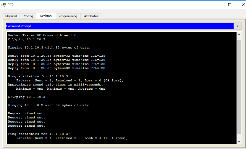
We will assign static IPs to the machines for now to show that computers inside each VLANs have connectivity with each other but they are unable to reach computers on a different VLAN.
PC2 has an IP of 10.1.10.2 and it belongs to VLAN 20, it can successfully ping PC3 which is on the same VLAN 20 but cannot ping PC1 and PC2 which are on VLAN 10.

Router on a Stick Configuration
- Use the interface type number.subint command in global configuration mode to create a unique subinterface for each VLAN to be routed.
- Use the encapsulation dot1q vlan_id command to enable 802.1Q trunking and associate each VLAN with the subinterface.
- Use the ip address address mask command to configure the IP settings.
We will now go inside the router to configure the 802.1Q trunk. It is advisable to use a router with a Gigabit Ethernet interface if you are handling large amounts of data transfer.
First thing is to bring up the trunk port:
Router#conf t
Router(config)#int fa0/0
Router(config-if)#no shut
%LINK-5-CHANGED: Interface FastEthernet0/0, changed state to up
Then, configure the subinterfaces for each VLAN on the trunk.
Router(config-if)#int fa0/0.10
Router(config-subif)#encapsulation dot1q 10
Router(config-subif)#ip address 10.1.10.1 255.255.255.0
Router(config-subif)#int fa0/0.20
Router(config-subif)#encapsulation dot1q 20
Router(config-subif)#ip address 10.1.20.1 255.255.255.0
Router(config-subif)#end
You can check if its already established routes to the VLAN subnets by using the show ip route command.
Router#show ip route
 Codes: C - connected, S - static, I - IGRP, R - RIP, M - mobile, B - BGP
 D - EIGRP, EX - EIGRP external, O - OSPF, IA - OSPF inter area
 N1 - OSPF NSSA external type 1, N2 - OSPF NSSA external type 2
 E1 - OSPF external type 1, E2 - OSPF external type 2, E - EGP
 i - IS-IS, L1 - IS-IS level-1, L2 - IS-IS level-2, ia - IS-IS inter area
 * - candidate default, U - per-user static route, o - ODR
 P - periodic downloaded static route

Gateway of last resort is not set

10.0.0.0/24 is subnetted, 2 subnets
 C 10.1.10.0 is directly connected, FastEthernet0/0.10
 C 10.1.20.0 is directly connected, FastEthernet0/0.20
Now, most Cisco routers do not attempt to negotiate trunking, so make sure you issue the switchport mode trunk command on the matching switch interface.
Switch#conf t
Switch(config)#int fa0/1
Switch(config-if)#switchport mode trunk
Now, let’s see if we can ping a machine from another VLAN. And as you can see on the image below, PC2 from VLAN 20 can now ping PC1 from VLAN 10.

Conclusions
This article briefly discussed the technology and process behind the Router-on-a-stick and demonstrated how you can configure a 802.1Q trunk link between a Cisco router and switch. The Router-on-a-stick configuration is mostly used in environments where there are no layer 3 switching, because it provides inter-VLAN routing services using a single router and one interface, making it cost-efficient.


